Extrusion Processes
Pipes, hoses, shopping bags, window profiles, the fibers in your clothes — the long, continuous plastic products all around you mostly come from one family of processes: extrusion. Have you ever wondered how something can be made by the mile?
On the Molding Processes page we covered the phases a plastic resin goes through to be transformed, and those same phases apply to extrusion. The main difference is that extrusion is a continuous (or semi-continuous) process, and rather than a mold it uses a die, which forms the desired cross-section — a tube, a profile, a sheet.
Here we’ll cover the following processes:
- Extrusion (general)
- Extrusion Screw Design
- Sheet and Film Extrusion
- Thermoforming
- Co-Extrusion
- Blown Film Extrusion
- Compounding
- Calendering
- Filament Extrusion and Spinning
- For Extrusion Blow Molding (EBM), see the Blow Processes page.
Extrusion
Extrusion is a process used to create objects with a fixed cross-sectional profile, in which a material is pushed or pulled through a die that has the desired cross-section. The two main advantages of this process over other manufacturing methods are its ability to create very complex cross-sections and to work with brittle materials, since the material is subjected only to compressive and shear (frictional) stresses. It also produces parts with an excellent surface finish.
Extrusion can be continuous (in theory producing an indefinitely long piece) or semi-continuous (producing many pieces). The process can be carried out with the material hot or cold.
Extrusion isn’t only for plastic resins; other commonly extruded materials include metals, ceramics, cement, modeling clay, and food products. Extruded products are generally called “extrudates.”
The screw — or screws, in the case of twin-screw extrusion — forces the resin through the die so that it takes on the desired shape. The extrudate cools and solidifies as it is pulled through the die or through a water bath.
A puller is used to provide the line tension that is essential to the overall quality of the extruded product. Pelletizers can also create that tension as they pull the extruded strands through to cut them.
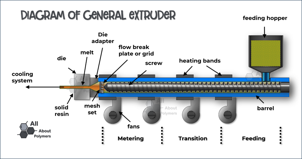
The puller must provide constant traction; otherwise, the result is variation in the cuts or a distorted product. In some cases (such as fiber-reinforced tubing) the extrudate is pulled through a very long die, in a process called pultrusion.
Extrusion is commonly used to add colorant to molten plastic, creating specific custom colors.
Hollow cavities cannot be formed in the center of the extrudate using a simple, flat extrusion die, because there would be no way to support the central section within the die. Instead, the die takes the form of a block with depth, beginning with a shaped profile that supports the central section, as shown below.
The shape of the die determines what you can make. Flat dies produce films and sheets; profile dies without a mandrel produce solid pieces such as rods and pelletized resin compounds; and mandrel dies produce hollow shapes such as hoses and pipe. This makes extrusion an efficient way to manufacture profiles and semi-finished products — also called stock shapes — with large wall thicknesses, in a wide range of dimensions and colors.
“Extrusion is a process used to create objects with a fixed cross-sectional profile, in which a material is pushed or pulled through a die.”
Extrusion Screw Design
To really understand extrusion, it helps to understand the tooling working inside the equipment — and the most important piece is the screw. It is the screw that conveys the resin, melts it, mixes it, and builds the pressure that forces it through the die, so its design largely shapes how the whole process performs.
The length of a screw is expressed in terms of its length-to-diameter ratio (L/D).
For crystalline plastic resins, an L/D of 24:1 is very common.
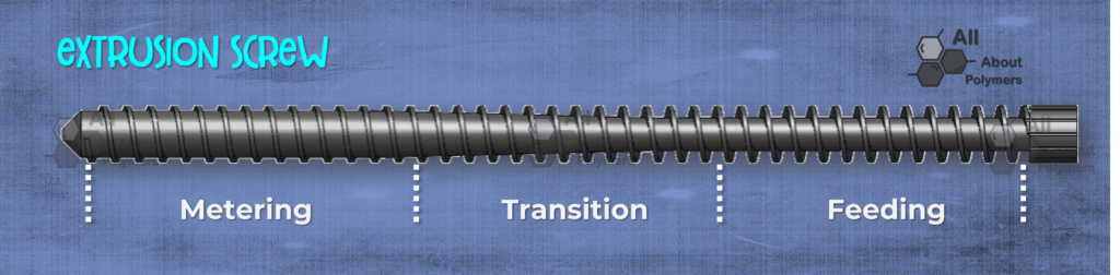
The geometry of extrusion screws can vary. The most widely used are three-zone screws and barrier screws.
The three zones are:
- Feed section
- Compression (transition) section
- Metering section
Feed
The feed section is where the unmelted polymer enters the barrel. As the screw rotates, any material between the screw surface and the barrel wall is conveyed along the barrel — depending on the direction of rotation — and begins to melt as it moves forward.
Compression
In the compression section, the gap between the screw and the barrel narrows with each rotation, so the resin pellets melt mainly through friction and conveying. As the flight depth decreases, gases — air and gases given off by the resin itself — and volatiles such as moisture are pushed back toward the hopper.
The length of the compression section depends on the polymer being extruded. An extreme example is PVC (polyvinyl chloride), which requires the compression section to span the full length of the screw; by contrast, for crystalline resins the required compression section can be as little as one-third of the screw length.
Metering
In the metering section, the screw’s flight depth is at its shortest but stays constant throughout, which homogenizes the melt and builds the pressure needed to convey it to the forming area — such as a block or a film die — where it will be formed. This pressure depends on the length of the metering section.
A screw’s compression ratio is calculated by dividing the flight depth in the feed section by the flight depth in the metering section.
Mixing
The mixing effect of single-screw extruders is limited. For proper dispersion of additives such as stabilizers, anti-blocking agents, lubricants, and so on, special mixing elements are needed. There are several types of mixing sections, such as Maddock, Egan, pineapple, and others.
Extrusion Screw Configurations
An extrusion machine can carry from one up to four screws, with single-screw and twin-screw being the most widely used configurations.
Single-screw extrusion is one of the main operations in polymer processing and a key component of many other processing operations. The main goal of single-screw extrusion is to build pressure in the molten polymer so that it can be extruded through the die. Most machines are plasticating: they are fed polymer in pellet or powder form and melt it while building pressure.
Twin-screw extrusion, on the other hand, is used extensively for mixing, compounding, or reacting polymeric materials. The flexibility of a twin-screw extruder allows it to be designed for specific compounds, since the screws can be co-rotating or counter-rotating, intermeshing or non-intermeshing. In addition, the screw configurations themselves can vary, using conveying elements, reverse-conveying elements, kneading blocks, mixing zones, and other designs to suit the proper processing of the compound or resin being run.
Intermeshing Screws
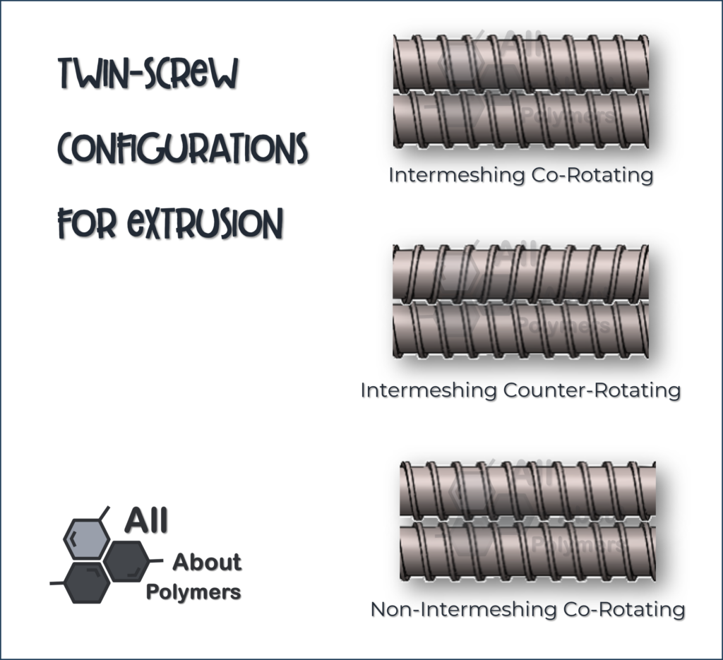
The two screws can be intermeshing or non-intermeshing; the intermeshing ones can rotate in the same direction (co-rotating) or in opposite directions (counter-rotating).
In intermeshing screws, as the name says, the flights of one screw are interleaved with those of the other, working against each other.
When the screws are intermeshing and co-rotating, one screw wipes the other without creating much friction against the barrel walls. Co-rotating intermeshing twin-screw extruders are the most common in industry.
When intermeshing screws are counter-rotating, the melt is squeezed in the gap between the screws, and the main objective is mixing, devolatilization, and reactive extrusion.
Barrier Screws
Another form of efficient mixing is barrier screws. This type of screw forces the polymer over the screw flights into a secondary channel.
Sheet and Film Extrusion
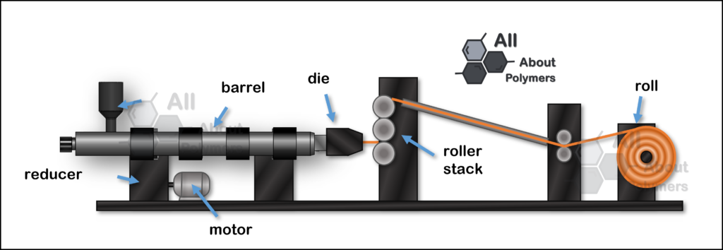
In both die types, a constant, uniform flow must be ensured across the entire cross-sectional area of the die. Cooling is normally done by pulling the melt through a set of chill rolls (or a calender). In sheet extrusion, these rolls not only provide the necessary cooling but also determine the sheet thickness and surface texture. Co-extrusion is often used to apply one or more layers on top of a base material to obtain specific properties, such as UV absorption, texture, oxygen barrier, or energy reflection.
Thermoforming
A common post-extrusion process for plastic sheet is thermoforming, in which the sheet is heated until it softens and is then formed by pressure or vacuum over a mold into a new shape. When vacuum is used, this is often described as vacuum forming. Orientation — that is, the available capacity/density of sheet that can be drawn into the mold, which can vary at depths typically from 1 to 90 cm (0.4 to 35 in)— is very important and greatly affects the forming cycle times for most plastics.
Co-Extrusion
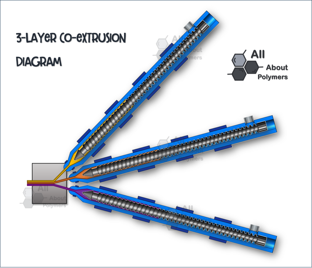
In practice, many films, sheets, tubes, and other shapes are extruded with several layers; this allows optimization of a wide range of properties, such as oxygen barrier, mechanical strength, and so on. This is achieved by co-extrusion, which consists of having two or more extruders feed a single die that joins the different extruded layers.
The main difficulty of co-extrusion is bonding the layers so that their properties combine. This is done with intermediate adhesive (tie) layers that join two otherwise incompatible resins; this is critical, otherwise the structure would separate.
There are two broad types of co-extrusion die: single and multiple. Both rely on a separate extruder for each polymer chemistry. In multiple dies, each layer is extruded separately and only combines just before the die lips. This type of die is expensive because of the complex tooling required, but it can mitigate large differences in rheological behavior between the various layers. Single dies form the multiple layers into one, allowing contact between the polymer layers for a longer period of time. This ensures optimal bonding, but as a result greater compatibility between the polymers is needed.
Two types of processing defects can occur during co-extrusion. The first is interface instability, causing undesired interface shapes. This can cause “encapsulation” of the higher-viscosity melt by the lower-viscosity melt, leading to poor final performance of the extruded part. The severity of this type of defect is proportional to the difference in viscosities between the two polymer melts. The other type of defect forms oscillations in the melt flow, causing small wave-like patterns on the surface of the melt and reducing optical clarity.
“Co-extrusion consists of having two or more extruders feed a single die that joins the different extruded layers.”
Blown Film Extrusion
The manufacture of plastic film for products such as shopping bags and continuous sheeting is accomplished using a blown film line.
This process is the same as a normal extrusion process but with a special die through which air is blown. There are three main types of die used in this process: annular (or crosshead), spider, and spiral. Annular dies are the simplest and rely on the polymer melt flowing around the entire cross-section of the die before exiting; this can result in uneven flow. Spider dies consist of a central mandrel attached to the outer ring through a series of “legs” or arms; and although the flow is more symmetrical than with annular dies, this type of die forms a series of weld lines that weaken the film. Spiral dies eliminate the issue of weld lines and asymmetric flow, but they are by far the most complex.
The melt is cooled slightly before the die exit to produce a semi-solid tube. Drawing and blowing cause the film of the extruded tube to thin, aligning the polymer’s molecular chains in the direction of greatest stress. If the film has more draw tension than blow tension (the final tube diameter is close to the extruded diameter), the polymer molecules will be highly aligned in the draw direction, making it stronger in this direction and weaker in the blow direction. Conversely, a film whose final diameter is significantly larger than the extruded diameter will have more strength in the transverse direction and less in the draw direction.
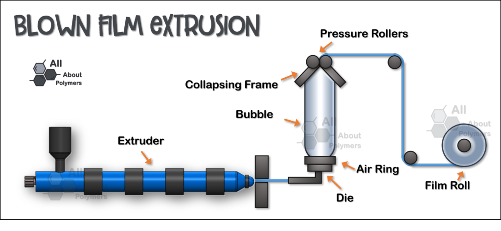
Pressurized air is introduced through the extrusion die so that, after the polymer melt exits the die lip, it expands in circumference. The tube is also drawn lengthwise faster than it is being extruded. This leads to thinning of the film as it expands both in the machine direction and in the transverse (hoop) direction. The ratio of the blown diameter to the extruded diameter is known as the blow-up ratio, and it affects the resulting physical properties of the film, such as stiffness and strength. Film thickness and blow-up ratio can be varied by adjusting roller speed, the internal pressure in the bubble, and the melt extrusion speed.
As the film is stretched upward, it is cooled by a ring of air blowers so that the melt becomes an amorphous viscoelastic solid, and then a semi-crystalline solid, at what is known as the frost line. After solidification, the blown film tube continues to cool as it is drawn upward by several sets of rolls, deflating the film to form a lay-flat tube. The flat film is wound onto a reel before any further finishing or shipping. The film line height is often 10 times the bubble diameter or more; film lines exceeding 30 meters (98 feet) are possible.
Once the film tube has cooled completely, it is taken up by several nip rolls. The width of the resulting folded lay-flat film equals half the circumference of the bubble. The film is then wound, either as a lay-flat tube or immediately slit into two separate pieces. At this point, the film is ready for further processing, such as printing or slitting.
“Blown film extrusion is the same as a normal extrusion process but with a special die through which air is blown”
Compounding
Compounding by extrusion consists of preparing plastic formulations by mixing additives and/or fillers with one or more polymers; these mixtures are generally metered through feeders or hoppers into the extruder, where the plastic resins melt, allowing the fillers and additives to be distributed throughout their molecular networks to form the compound.
Kneaders and twin-screw extruders (co-rotating and counter-rotating) with internal mixing zones are the most common for compounding in the plastics industry.
The extrudate, which looks like long plastic strands, is cooled at the die exit in a water bath and then cut into pellets or pulverized.
Calendering
The calendering process is essentially the extrusion of a mass of material between successive pairs of co-rotating rolls. It is used to make film and sheet from materials that are sensitive to prolonged heat and shear, such as those encountered in extrusion processes. The most widely used materials in this process are polyvinyl chloride (PVC), ethylene-vinyl acetate copolymers (EVA), high-molecular-weight polyethylenes (PE), and acrylonitrile-butadiene-styrene terpolymers (ABS).
Most plastic calenders consist of four heated rolls arranged in an inverted “L” configuration. Other roll configurations use vertical lines of two, three, or four rolls, and other arrangements — all depending on what is being processed.
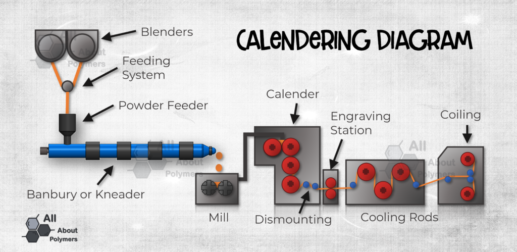
A complete calendering process line includes a mixing and melting unit, the calender, take-off rolls, an embossing section, cooling rolls, edge trimming, and finally, winding.
On certain lines, some transverse stretching can be applied to the web with diverging rolls that force the edges of the web outward to orient the sheet or film. This improves optical properties and mechanical strength.
In typical calendering of rigid PVC sheet and EVA foams, the resin is first mixed with various additives — in the case of PVC, processing aids, stabilizers, pigments, and lubricants; in the case of EVA, blowing agents, fillers, and pigments. The mixture is melted to disperse the additives and masticate the resin to a viscous state. This can be done in a Banbury mixer, kneader, planetary extruder, or twin-screw extruder. The molten resin leaves these units as a continuous strip or in chunks. While still hot, the molten resin is conveyed to the calender feed line.
The action of the hot rolls forms a rolling bank of resin. The heat and pressure of the rolls work the material in the bank to a uniform viscosity and temperature. The material is compressed through the nip into a wider, thinner sheet, which is carried by one of the rolls to the next nip, finally reaching optimal consistency and viscosity and giving the final sheet uniform strength, gauge, and quality.
To ease the flow of material through the calender, each successive roll is somewhat hotter than the previous one. Since the resin tends to stick to the hotter surface, this causes it to pass from roll to roll.
The calendering process is widely used to make rigid and flexible PVC sheet and EVA foams, such as the well-known craft foam (“foamy”) used for school projects, or more engineered foams such as athletic shoe soles.
Filament Extrusion and Spinning
Spinning is a manufacturing process for making fibers from a polymer. It is a specialized form of extrusion that uses a spinneret to form multiple continuous filaments.
There are many forms of spinning: wet, dry, dry-jet wet, melt, reaction, and electrospinning.
Fiber Spinning
This method is used to make synthetic fibers for various industries. There are three main types of fiber spinning: melt, solution, and reaction. In this type of spinning, a liquid polymer is extruded through a die with many small holes in a spinneret to form thin filaments. As they advance, the filaments solidify and are then combined with other filaments to form yarns, or are drawn to orient the polymer chains for better mechanical properties.
Melt Spinning
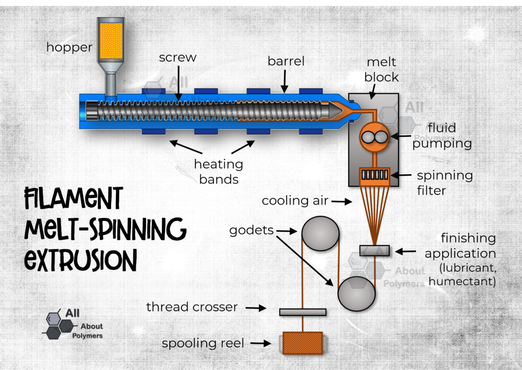
This is the most common form of fiber spinning. In this process, already-molten polymer is used, or the polymer is melted from pellet form. At the extrusion die exit, the filaments are cooled in water, in air, or with chill rolls.
The filaments can be gathered or twisted to form a yarn. Before the yarn is wound onto its bobbin, it is generally treated with water or a wetting agent and a lubricant to ease its later use.
Spinneret plates can have up to 80,000 holes, spaced less than a millimeter apart (≈ less than 0.04 in). Some other spinnerets have ultrafine capillaries 50 micrometers (2 mils) in diameter.
The polymers most used in melt spinning are polyethylene (PE), polypropylene (PP), and nylon or polyamide (PA).
Solution Spinning
This method is used when the desired polymer does not form a stable melt. These polymers are dissolved in a solution to make them liquid instead of melting them. The two main forms of solution spinning are dry and wet.
In dry solution spinning, the polymer is dissolved in a volatile solvent. Once dissolved, the polymer solution is extruded through a spinneret surrounded by a drying tower. The solution goes through a drying process in which the solvent is evaporated.
In wet solution spinning, the polymer is dissolved in a non-volatile solvent. The spinneret, placed in a coagulation bath, causes the fiber to precipitate.
The liquid in the coagulation bath is selected so that the solvent is soluble in it but the polymer is not. This allows the polymer to precipitate and form the solid filaments required. The solvent can be recovered at the end of the process. The drag of the coagulation liquid on the filament significantly reduces the production rate, making it a slower process than melt spinning or dry solution spinning.
Reaction Spinning
This process involves the cross-linking of monomers or pre-polymers to create a new polymer using an extended chain reaction.
This process is similar to dry solution spinning, but with an additional step. During polymerization, the shorter monomer chains react to form longer, interconnected chains — this cross-linking is what allows polymer fibers with good mechanical properties.
This is the process used to make elastane (Spandex) fibers. Reaction spinning is used to cross-link a flexible polymer with a rigid one, producing a strong, durable, and stretchable fiber.